

odie
-
Content Count
17 -
Joined
-
Last visited
Content Type
Profiles
Forums
Blogs
Gallery
Posts posted by odie
-
-
The truck has auto headlights, when they come on all the HVAC controls illuminate. There is a rotary dimmer switch that I can dim the HVAC lights with if I so choose.
I know exactly which wire sends the 12V signal to these lights... if I tap this wire I should be safe even if the dimmer is used?
If you are trying to dim the radio display like your HVAc controls by using your dimmer knob, I don't think it will work as the radio is not capable of illumination dimming like your HVAC controls.. For instance, on my truck when the headlights are on the map dims to a predetermined level and the skyscape goes from light blue to dark blue with stars.. If you have a manual hedlight/ marker light switch, as I do even with auto headlamp, you could tap into that to use as your illumination wire to your stereo..
-
what do you mean?
The camera works... when you go reverse it works correctly.
but when i go to Menu and switch to Camera it is just black.
If the camera only shows picture when you have the transmission in REVERSE, I would guess that your radio installer use the reverse wire on your taillight to power the back up camera.. Therefore your camera only gets 12V power when your reverse light is on.. The back up camera needs to be powered through a switched 12V power source, just like your radio..
Odie
-
most of these new cars do not have the standard illum wire, all the modules (radio's, climate controls, and guage clusters...) get the dimming signal from the vehicles can-bus system, and the data modules that come with all of these expensive wire harnesses are supposed to decode the diming signal from the can bus and convert it to something that the radio will understand. however there are a few vehicles that this doesnt work for (havent really been able to get a reason why) but you will need to find somewhere else to get the signal, if the car does not have auto lights, then you can tap into the parking light wire from the switch(only if positive trigger) or you can tgo to any dash light(it would have to be one of the wires for the light bulb itsself, like an ashtray light) or if all else fails, as a last resort you can go and run a wire to one of the parking lights or headlights themselves (if the car uses negitive trigger, then you would have to use a relay to switch the polarity)
My bad... Ya learn something new every day.. Here I thought my 05 Ford was new.. I guess I'm just dillusional.. LOL
Odie
-
Hi Folks,
A few months ago I installed an X920BT in my 2008 Hummer H3 using the GMOS-01 adapter to retain OnStar and chimes.
Everything about the install works great except for the day / night mode on the X920BT. I checked and double checked my connections according to the X920BT and GMOS-01 installation guides and they are correct; however, night mode still does not work.
I have Googled around and searched on this forum and have read that the illumination wire / circuit on the GMOS devices do not work and that the solution is to hard wire in to the illumination wire of your vehicle. The problem with the H3 is that the illumination wire comes over the CAN bus and is not a regular 12v signal wire.
I figured I could just tap into the dimmer wire going to my HVAC controls (which is a 12v wire) to achieve the same effect as the illumination wire, but I read somewhere on this forum that it could potentially brick my X920BT if the dimmer switch is used.
Is it safe for me to use the dimmer circuit on the H3 to get the headunit to switch from day to night mode? If not, is there another alternative for me?
Thanks.
If you tunrn your headlights on and your HVAC controls/display illuminate/dim, it would be safe to tap into that wire for your illumination wire.. It is the same as your illumination wire going to your stock radio, which if you get a pin out diagram, you can tap into that wire also..
Odie
-
Hi I am going to purchase a Avic X920BT and was wondering what I will need to wire it and mount it?
I also want to be able to use a Ipod Touch
Thanks for your help
Jason
I have posted a pretty lengthy description of my installation using the same radio and vehicle.. You can find it on X series subforum under general..
Odie
-
The "classic" destiction is on 6th and 7th gen iPods only. People mistakingly refer to all "original looking" as classics but that is not correct. The 4th Gen is not supported period. The minimal "original looking" iPod is the first gen iPod video, also known as the 5th Gen and from there on.
Just wondering which generation/version would a brand new iPod classic be??? If an iPod classic is not 5th generation or version 2.02, is it possible to program/ upload version 2.02 onto it and if so which webite would have it?? It would be nice to post this & the answers onto a sticky so it stays on top for easier reference for other users..
Odie
-
I have a factory Bose system (with factory amp). How do I connect the harness to the actual head unit? The only A/V connections on the head unit that I see are RCA ones and there are no RCA connection on the PAC OS-4.
On the power harness (black plug that hooks into the head unit) there are a bunch of wires coming off of it, 8 of which are for the speakers.. If you have the install manual it will explain it.. There are PDF files on this site that has the install for your particular radio..
Odie
-
I just received my Pioneer X920BT and PAC OS-4 wiring harness and am planning to install it in my 2007 Tahoe this weekend. I installed a Pioneer AVIC-D3, so I feel like I have some sort of experience with installation, but I'm a little confused about one thing: what do the RCA connections from the head unit connect to on the wiring harness, or do they not connect to anything? I remember having RCA connections between the wiring harness and the head unit on the D3 install, so I'm just not sure where to plug the RCA connections from the head unit. Any help is greatly appreciated! Thank you.
If you have aftermarket speakers/subwoofer/amp: use the rca cables, othwise stick with the standard speaker wires on the harness..
Odie
-
im a bit confused with the pac unit I have. it said to tie the white wire of the pac unit into pin 18. I did that, but does that wire have to tie into any of the wires coming off of the pioneer harness?
The Pac unit has a little 3.5mm plug that goes into the back of the pioneer unit, so no splicing into the radio harness..
-
make sure to isolate the wire from the vehicle's computer with a diode or else the reverse lights will be on the whole time the switch is on while the vehicle is driving down the road
I guess what I meant to say is find a switched 12v power source and hook your reverse sensor wire to it, instead of the actual reverse sensor wire. with a toggle switch you can change it from full screen to half screen.. I was also thinking you could install a camera on you front bumper (i.e. a large truck) with a switch to choose between front view and rear view..
-
LMAO!!!!
Hindsight being 20/20. I should have taken a bunch of pics while assembling the harness.. Stupid me.. But I learned something new.. When you disconnect the power harness from the unit, you have to turn off the rear camera settings, otherwise you get the "image on screen may be reversed" meassage..
-
If you put it in reverse and get a full screen image, why not just put in a toggle switch with 12v going through it to the reverse gear sensor wire.. That way you're tricking the radio into thinking you're going in reverse constantly until you toggle the switch off.. Just an idea..
Odie
-
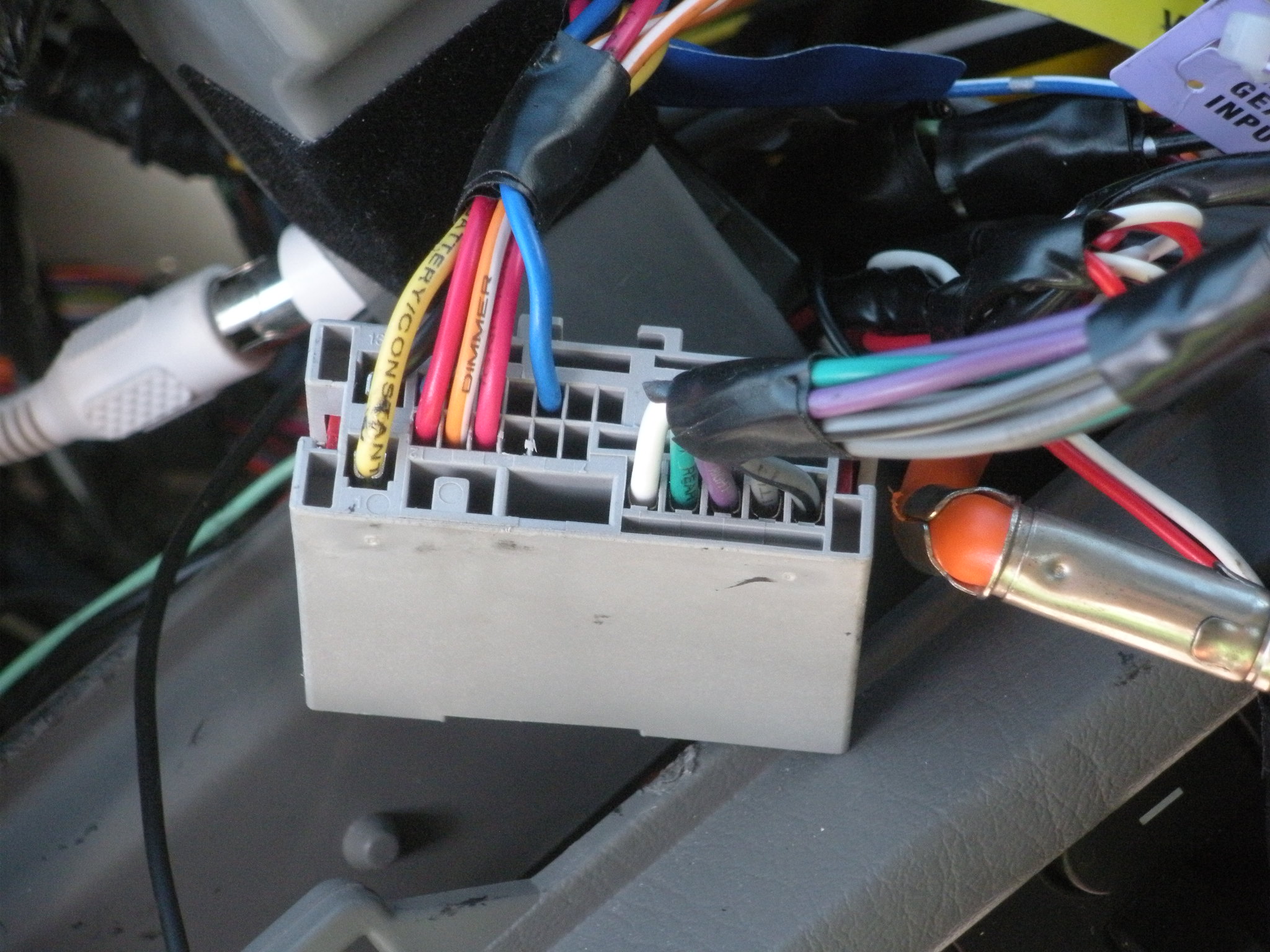
Here's some pics... What a PITA to take everything apart.. Hope you're happy..
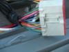
This is a pic of vehicle side harness.. Note the colors of the wires..
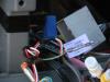
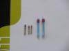
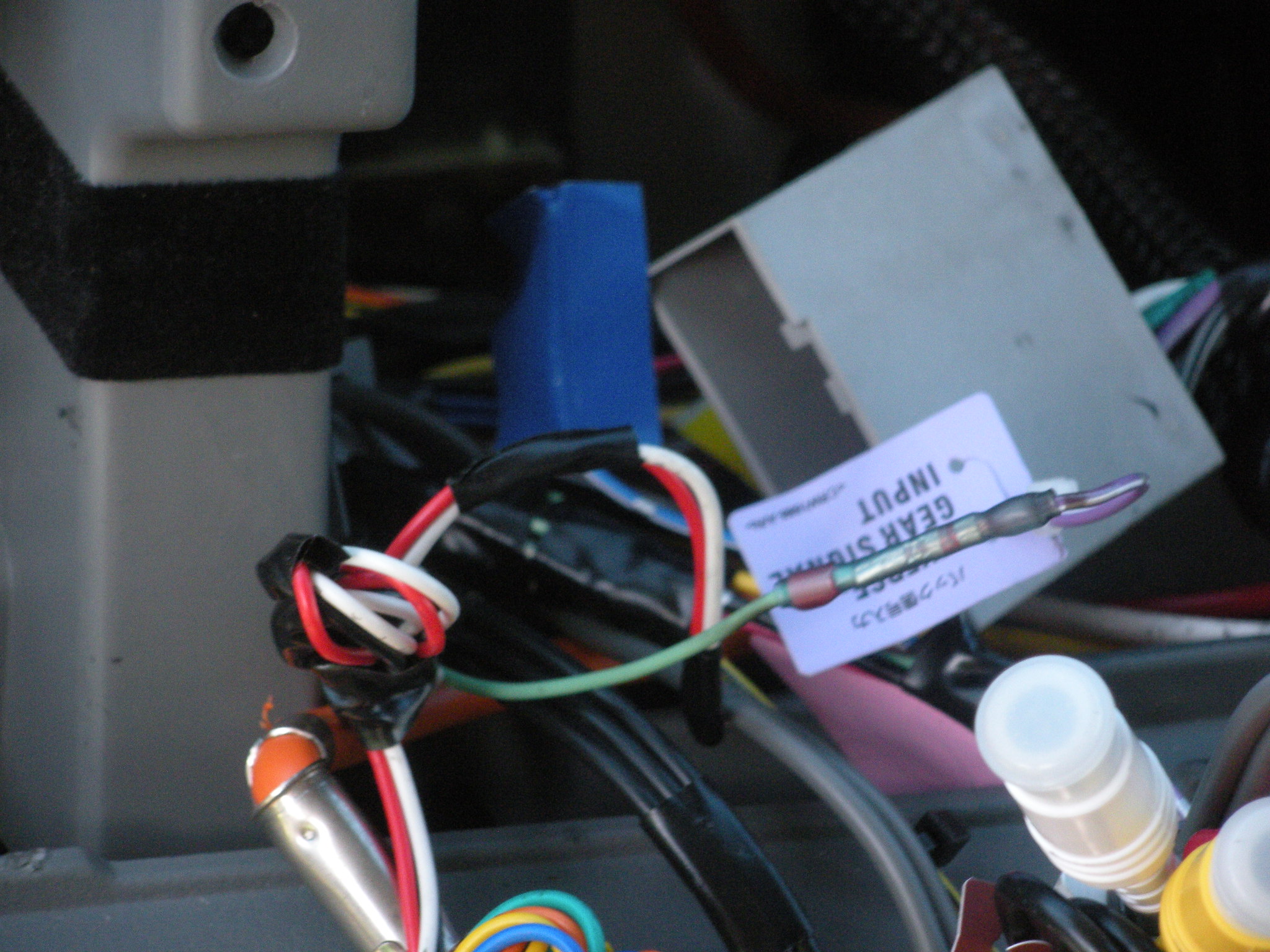
This is a pic of reverse gear splice into the radio harness. Note the nice splice..
This is a pic of reverse wire. The wire at the top of the pic is actually pink/black.. I used the leftover green parking brake wire for the splice as you can tell at the top left corner of the pic..
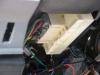
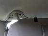
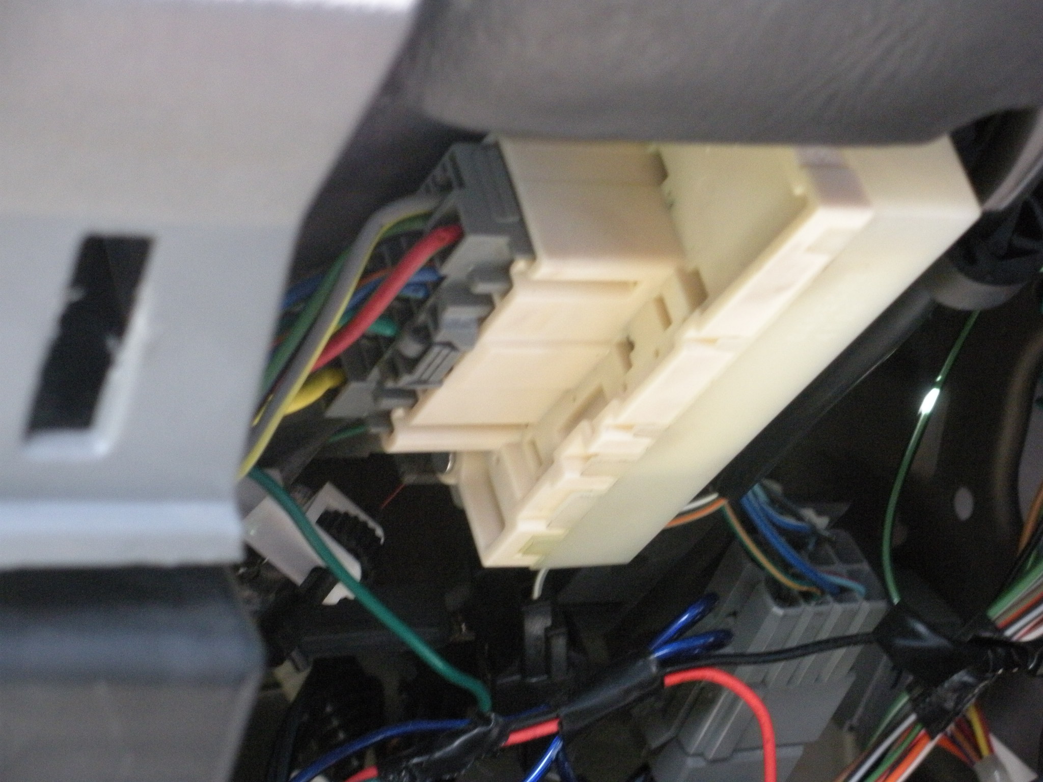
This is where the reverse wire input connector plugs in. Underneath the steering column..
Pretty self explantatory..
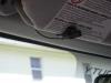
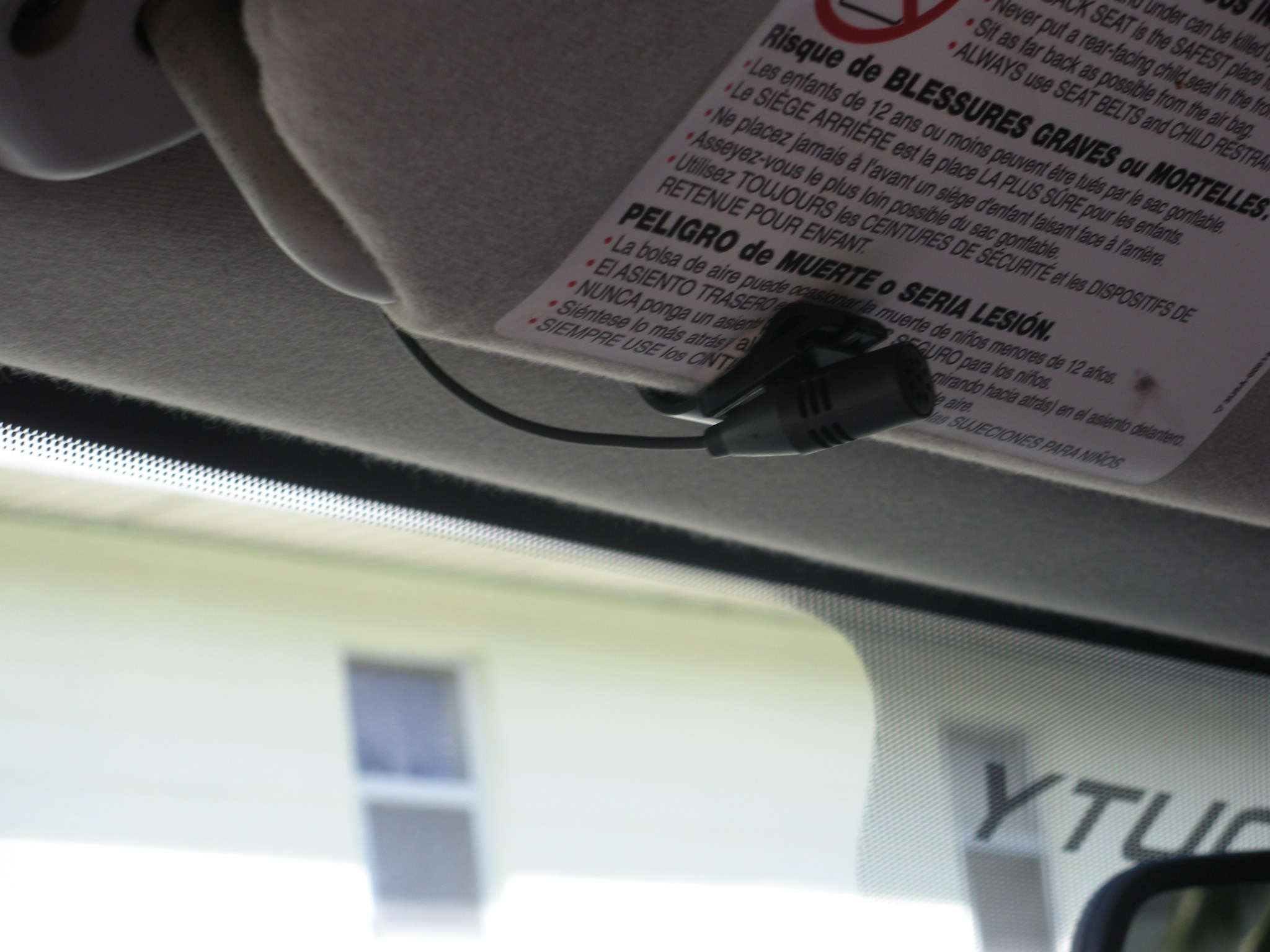
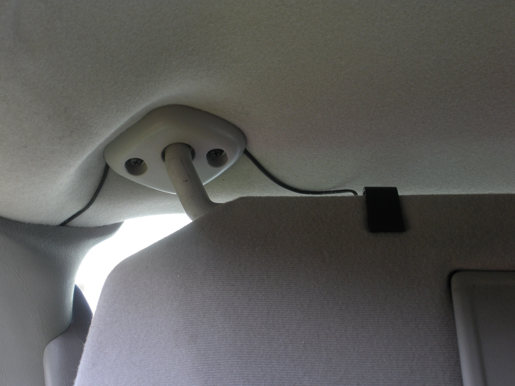
Tucked the wire underneath the visor mount for a cleaner look.. From there I tucked it behind the door seal..

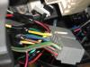
This is a pic of the back of the Metra radio harness that was modified.. Note the color and pin positions, this is important when reading my first post..
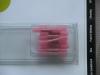
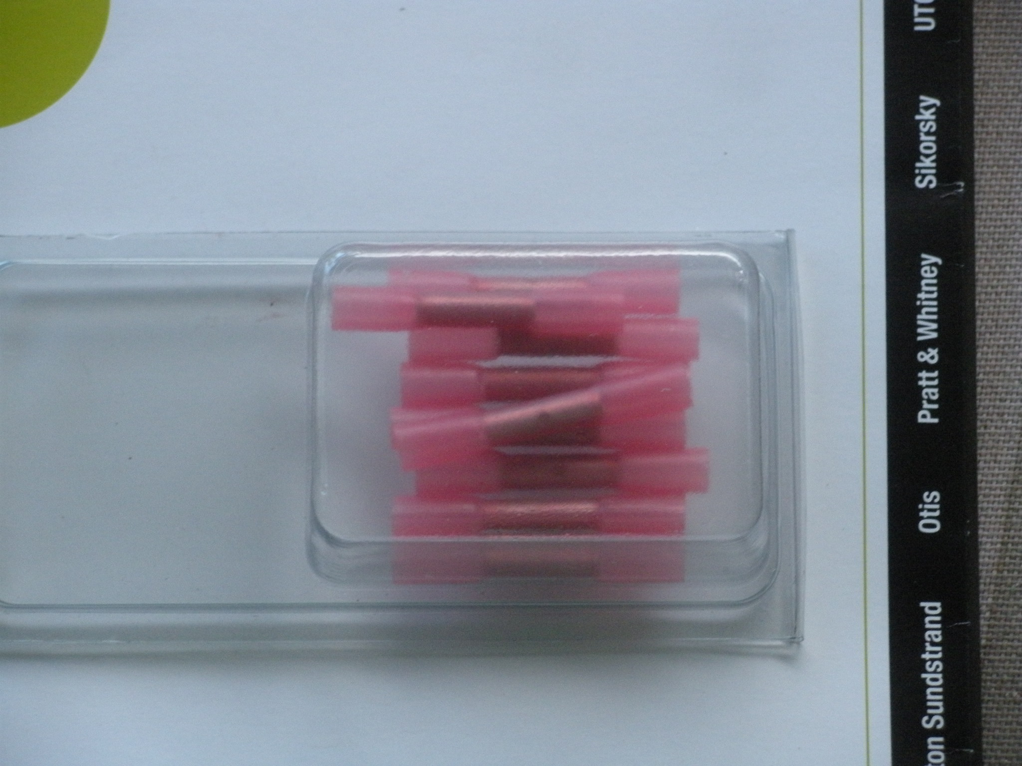
These are the crappy butt connectors I found at the auto parts store..
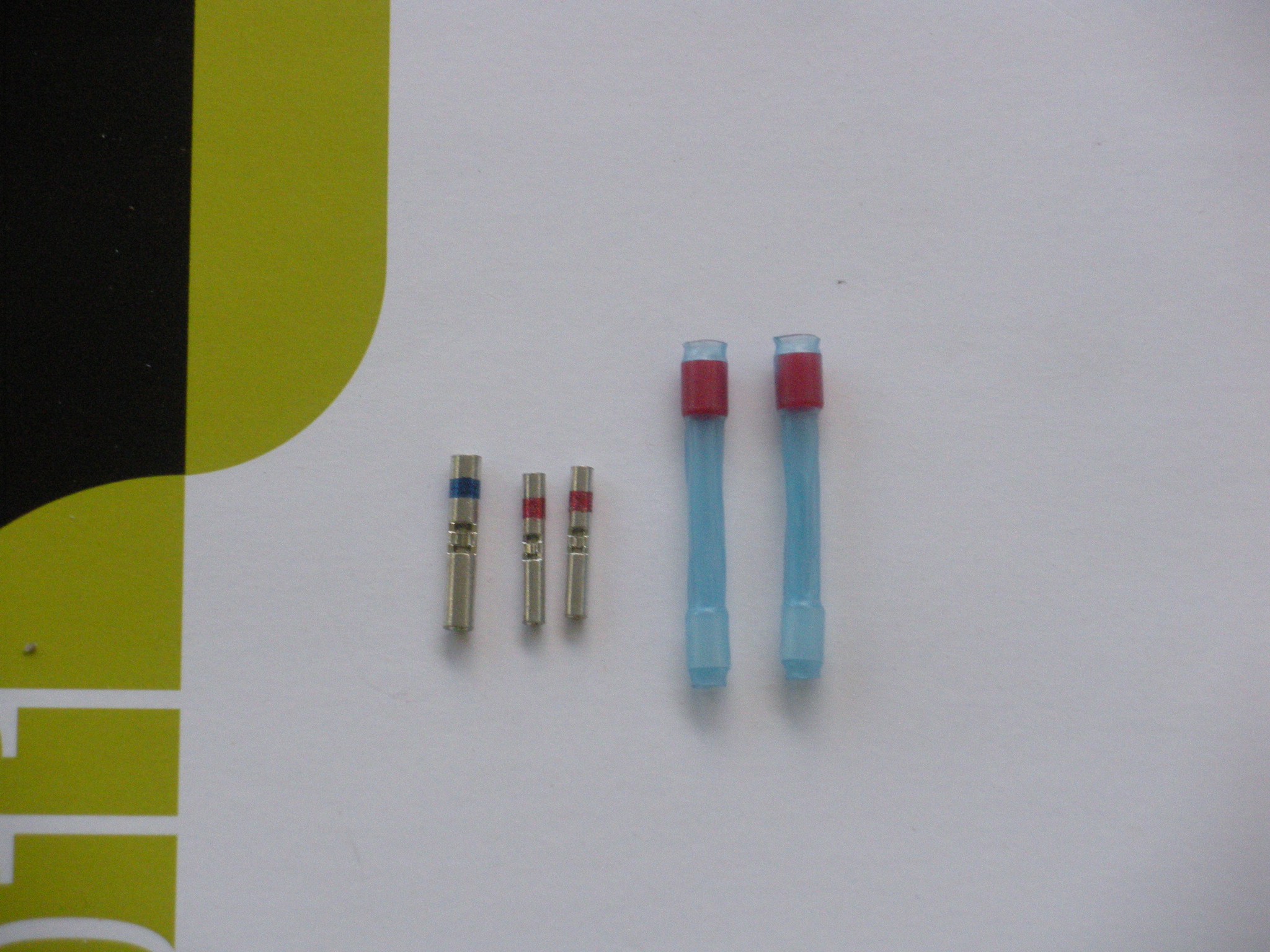
Here are the splices I got from work. Alot smaller and easier to work with..
Hope this helps someone with the install. Again, any questions please post..
Odie
-
if you use the scosche harness, you wont need to buy a second harness as there are a bunch of extra brown wires that can be used to repin into what ever pin location you want them in (there is actually one already in the pin 18 slot for the steering wheel control wire)
scosche part number FDK11B (this also comes with the plug adapter that you will need if you have the factory sub under the rear seat)
and i disagree about the type of connectors you can use, automotive grade connectors should have no problem holding up in any automotive application, its the actual way of securing(crimping)the wires that usually lead to problems .if you want better than that then you should solder and tape all connections as that will be the best possible way of wiring the two harnesses together and having a problem free install.
Wish I had known about the Scosche harness earlier.... LOL
The only splices I could find at Advance Auto were 20 gauge and up, butt connectors with cheap heat shrink.. They were way to large for all the wires except for ground and power.. I will post up pics of the splices I used later today.. A lot more streamlined with a factory finished look..
Odie
-
pics or it never happened

Now that you called me out... I'll take the dash apart to take pictures here in a little bit..
Odie
-
I just installed a X920BT in my 2005 Ford F-350. Unfortunately I didn't take any pictures, here is my advice whendoing this install.. The whole install took 2 days. I am sure you could do it faster, but I prefered to take my time. The first day was spent wiring the harness. I used 2 Metra aftermarket radio harnesses. Make sure it is a 24 pin connector. I have heard some bad things about Metra so I verified each wire color. You will need 2 of these connectors because you will need to cannibalize 3 of the smaller pins off of the 2nd connector to do a clean install.
Here is the wiring setup you need to do:
Aftermarket Stock Harness
Yellow Green/Purple 12V constant
(right) Red Pink 12V ignition
(left) Red Black Ground
Black Black/light Green Ground
Orange/White Blue/Red 12V illumination
(left) Blue Blue/Red steering wheel remote
(right) Blue Grey/ Black vss lead
Front Speakers
White/Black Blue/White left neg.
Grey/ Black Green/Orange right neg.
White Orange/light Green left pos.
Grey White/light Green right pos.
Rear Speakers
Green/Black Tan/Yellow left neg.
Purple/Black Brown/Pink right neg.
Green Grey/light Blue left pos.
Purple Orange/Red right pos.
Some notes to consider, the after market harness does not have pins for steering wheel remote, or Vss lead. You will have to take the 2nd harness apart to use the leads. I used the blue wire & inserted it into pin 18 spot for steering wheel remote, removed the blue wire off the 1st harness and re-installed it into pin 14 spot for VSS lead.
I also inserted a 2nd red wire into pin 15 spot for a 2nd 12v ignition source for either backup camera or XM module. If you look at the back of your stock harness it will all make sense.
To remove the pins you need to push the 2 red tsbs on the back of the connector forward. Use a scribe and pull the internal red piece completely out. You will use a scribe and hod up the locking tab for the pin while pulling the pin out of the connector. Once you have all the pins where you need them reinsert the red plastic piece.
When you splice the aftermarket harness to your radio harness, use only quality aircraft/ electronics grade splices, not automotive. this makes a big difference, I see alot of people with connection/ loose ground problems.. Don't skimp!!!!!!
Once all the connections are finished I zip tied and wrapped all the wires into a nice tight, neat bundle.
I spliced the Pac remote module into the harness, power to the 12v ignition, ground to ground, and white wire to right side blue wire (pin 18).
To hook up the reverse sense wire, I spliced off of the Pink/Black wire that can be found going from the white connector on the bottom of the steering column going to the back of the fuse box.
Hope this helps someone, if you have any questions, just post and I'll repley back promptly..
Odie


Boyo Camera Stops Working When Engine Starts
in Problems/Troubleshooting
Posted
Try switching the polarity to GND, and see if it fixes.. Did the camera work after the installer finished the job??
Also check to see where the camera power wire is connected. (red wire). it needs to be hookes up to a switched 12V source, just like your radio..
Odie