Search Archive

DucatiBoy Circuit Ordering Discussion Thread

By wishbone · May 04, 2006in Hacks/Mods💬 196 posts👁️ 46,256 views
Page 1 of 8
Posted May 04, 2006 · 02:44 UTC#1
Done.. thanks for doing this!! I've been battling with the bypass for awhile so I'm glad to see someone make it that much easier. Thanks again.
Posted May 04, 2006 · 12:05 UTC#2
Ok we already have had one person try to use a credit card to pay me for these. I thought I was clear in my post above. Please don't take this to be mean, and I don't want to come off as a schmuck either. So if it does I apologize.

If you use paypal and try to use a credit card to get one of these (at this time) your payment will be denied by me. I'm not set up to take credit cards and if I upgrade to a business account it will cost me for every transfer and I'm not doing that at this time. I may some time in the future if this takes off.... but at this time, bank transfers only.

Sorry. If you only have paypal with a creidt card, then PM me and I'll send you an address to mail me a check.

I know this might sound like a small time operation (not taking credit cards and all)... well it is. It's just me and I normally don't sell anything over the internet. :)

And if you want to know how dedicated to you people I am, in order to test this as much as possible and get these out as fast as possible, it's 80 deg and sunny here in lovely NJ and I'm leaving the bike at home and taking the truck, just to test as much as possible. See how dedicated I am? :)
Posted May 04, 2006 · 16:03 UTC#3
Just placed my order, hopefully I'm one of the 17!
I actually get my Z1 in a couple weeks so no rush. Hopefully the car shop will know what to do with it. They are aware of the lights trick so that's a plus.
Thanks!
Posted May 04, 2006 · 18:09 UTC#4
dj2ndnature said:
Just placed my order, hopefully I'm one of the 17!
I actually get my Z1 in a couple weeks so no rush. Hopefully the car shop will know what to do with it. They are aware of the lights trick so that's a plus.
Thanks!


Well, you don't have to worry. I only have 17 set for this initial "prototype" run, but since this looks like it's more popular than 17 I'm planning on a second run. If you are one of the first 17 I will ship them out next week. If you want one and send me money and you miss the first 17 (so far I have 8 orders), worse case is that I will not ship those till the week after. But I want to get the first run of boards in to make sure everything works.

If you sent a check to me please PM me I know people said they were sending checks, but then I set up paypal and some people changed... I'm starting to get confused. If you already sent out a check, please let me know.
Posted May 04, 2006 · 18:45 UTC#5
Have you considered selling it as a board and parts kit, or board and part list
for those of us good with building this type of thing? It might make things
easier for you....


Bill
Posted May 04, 2006 · 19:14 UTC#6
palter said:
Have you considered selling it as a board and parts kit, or board and part list
for those of us good with building this type of thing? It might make things
easier for you....

Bill


It would be easier for me, but at the moment would cost the same. So I don't know if anyone would want it. I'm probably going to have to bump up the price after these first 17 orders are done. The parts are all surface mount and very small (to get the size of this small, I was going for roubst not a low parts count). And there is a PIC with sepcial code, so a part list might be tough, cause you would need something to flash the processor with code. A parts kit might work too, but it might be as much work to collect the parts into bags and such and label them as it is to solder them.
Posted May 04, 2006 · 20:51 UTC#7
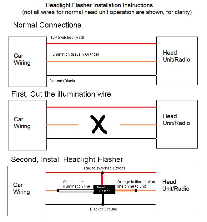
Here are the instructions for the installation of the headlight flasher module. Is this easy to understand? Look simple enough?

You might need to be registered to see the attached picture.

Here it is spelled out:

Connect the head unit exactly as described in your installation manual.

Cut the line going to the illumination wire.

Connect the white line from the head light flasher to the illumination line which came from the car.

Connect the orange wire to the illumination line which is going to the head unit.

Connect the red wire to the 12 Volt switched line

Connect the black wire to ground.

if you use your parking brake, you will want to leave that floating. If it's grounded (hooked correctly and the parking brake is on) the headlight flashing won't work. I have an automatic and never use the parking brake. If you use it, then just leave that line floating and tape it up. That way if you do use your parking brake it won't mess with what you did by flashing your headlights. Or put it on a toggle switch and normally leave it not connected to anything but when you switch the toggle switch it will connect it to ground.
Attached Files (1)
HeadlightFlasherInstruction.jpg
Posted May 04, 2006 · 22:55 UTC#8
Wow thanks for putting this together ducatiboy!
Posted May 05, 2006 · 15:11 UTC#9
Ducatiboy,
why not add a diode at the brain so the actual car lights won't even flash? The HU will be the only part get gets the 'flashed' input.
Posted May 05, 2006 · 16:00 UTC#10
rotorhead7 said:
Ducatiboy,
why not add a diode at the brain so the actual car lights won't even flash? The HU will be the only part get gets the 'flashed' input.


The headlights don't get "flashed". The "white" wire which goes to the car's wiring is a sense only wire (I designed the circuit to be very benign so it won't effect any of the car's systems with this installed). Nothing gets sent back into the car's electrical system. The orange wire from my circuit is the out line. I "fake" a headlight flash out on the orange wire, and after 10 seconds I "pass thought" what is sensed on the white input wire. No "diode" needed.

And most of the more modern cars have a dimmer control circuit in them so that when you turn on the headlights, those dimmer control circuits will see the headlights on and output a signal 0v-12v and change the duty cycle depending on your dimmer settings. If you back fed 12V into that, depending on the dimmer circuit, worse case you would hurt that circuit (maybe fry it) but I doubt it would turn the headlights on backwards through a car's dimmer circuit. I still designed my circuit to not backfeed anything back into what ever might be back in there. I believe it should be safe for any car (12V on all the time, 0v-12v signal, or a changing voltage, no matter what your car might have for a dimmer control, this will sense it and pass through an signal to the head unit).
Posted May 05, 2006 · 21:41 UTC#11
Just to re-iterate (since I got a PM or two on this issue):


My circuit will not actually flash your lights. Your headlights will not come on, your car won't know anything is hooked to it at all.

I was calling it a "light flasher" not cause it actually flashes your lights, but it makes your head unit think you did.

It does absolutely nothing to your car (other than draw about 5 miliamps of power, about the same amount an LED does in a remote control). When you first turn your car on, it will simulate the signal the head unit would normally see if you flashed your headlights. After 10 seconds have gone by, it watches what your lights are doing wether they are on or off. It does nothing to the car, it just watches. It then copies what your car is doing (have your lights on or off) and relays that signal to your head unit.

Make sense? I designed this circuit with a few more parts than absolutely necessary, which made it a bit bigger and more expensive for me, but it also make it quite a bit more robust against weird signals and voltage spikes and so on. I also did quite a lot of work (signal processing) in software on the processor so that I believe it will be compatible with every car out there. And won't hurt the car itself or any of your electronics if it's installed correctly. I also wanted to make it as fool proof of an install as possible.

Does that clear things up and make people feel better? :)
Posted May 06, 2006 · 01:26 UTC#12
So my confusion this far:

With the bypass/this circuit/whatever do you have to ground the brake wire? Do you need to do anything extra when using it or will it just work all the time? I tried to search through the now huge thread on this but it seems like different people are reporting different things.
Posted May 06, 2006 · 01:35 UTC#13
I don't think it matters if it is grounded or not. In my case I have it grounded and the turn on/off head lights trick works so Im sure this circuit will work with it grounded as well because all it is doing is simulating this same event.
Posted May 06, 2006 · 01:47 UTC#14
wishbone said:
So my confusion this far:

With the bypass/this circuit/whatever do you have to ground the brake wire? Do you need to do anything extra when using it or will it just work all the time? I tried to search through the now huge thread on this but it seems like different people are reporting different things.


If you ground it all the time, you will need to bypass the lockouts EVERY time you start the car. If you don't do the bypass one time and you try to do something like watch a dvd or something (with the parking brake grounded) then it will pop up that warning and that warning (about not having the parking brake correctly connected) will come up every time you start the car (it might not come up if you do the bypass on future start ups). I'm pretty sure this will happen, every part wasn't 100% tested by me.

If you connect the Z1 like the instructions say (grounded only when the parking brake is on) when you do the bypass you won't need to ground it. If you don't do the bypass one time, the worse thing that will happen would be that some features are locked out while moving and parking brake is off.

I was trying to access locked out features while moving one time, without bypassing them just having the parking brake permanently grounded and I got that "warning message" and it would come up every time I started the car and the only way to get rid of it was to reset the whole unit, even after I hooked up the parking brake like it's supposed to be installed. I still had to reset the unit.

I would recommend connecting the parking brake the way the instructions say to (or on a toggle switch under the dash). You don't need it grounded all the time to bypass any lockouts. And if you do need it some time you can activate it or not.
Posted May 06, 2006 · 04:35 UTC#15
ducatiboy said:
wishbone said:
So my confusion this far:

With the bypass/this circuit/whatever do you have to ground the brake wire? Do you need to do anything extra when using it or will it just work all the time? I tried to search through the now huge thread on this but it seems like different people are reporting different things.


If you ground it all the time, you will need to bypass the lockouts EVERY time you start the car. If you don't do the bypass one time and you try to do something like watch a dvd or something (with the parking brake grounded) then it will pop up that warning and that warning (about not having the parking brake correctly connected) will come up every time you start the car (it might not come up if you do the bypass on future start ups). I'm pretty sure this will happen, every part wasn't 100% tested by me.

If you connect the Z1 like the instructions say (grounded only when the parking brake is on) when you do the bypass you won't need to ground it. If you don't do the bypass one time, the worse thing that will happen would be that some features are locked out while moving and parking brake is off.

I was trying to access locked out features while moving one time, without bypassing them just having the parking brake permanently grounded and I got that "warning message" and it would come up every time I started the car and the only way to get rid of it was to reset the whole unit, even after I hooked up the parking brake like it's supposed to be installed. I still had to reset the unit.

I would recommend connecting the parking brake the way the instructions say to (or on a toggle switch under the dash). You don't need it grounded all the time to bypass any lockouts. And if you do need it some time you can activate it or not.


Yeah I've already tested the other possibilities of severing connections to the speed wire and leaving the ebrake grounded and none of them work for very long. What I'm hoping is with this bypass I can leave everything opportating as it should and have access to all the features of my unit while in motion regardless of whether or not the ebrake is on/off or I'm moving or not. Am I correct in understanding if I perform the bypass (or use your circuit at all times) it will just work regardless of what the other sensors (gps, speed, ebrake, gyro) are doing?
Posted May 06, 2006 · 05:47 UTC#16
Yes, you are correct, everything will work with all wiring hooked up correctly + this mod.
Posted May 06, 2006 · 06:01 UTC#17
ducatiboy, two things:
1. Can you please explain how a 12v to 0v duty cycle works? Just curious.
2. I would like to edit the sticky thread on TR7 programming to recommend this product instead (but leave the instructions in case.) Is this cool with you?

Thanks again for supporting the group with this cool adapter!
-Ed
Posted May 06, 2006 · 12:18 UTC#18
edrock200 said:

2. I would like to edit the sticky thread on TR7 programming to recommend this product instead (but leave the instructions in case.) Is this cool with you?


2. Sure, not a problem. I don't want to dethrone the TR7 cause I have a lot of respect for the PAC audio guys. But sure. If you want to, knock yourself out. I'm quickly running out of the initial run of boards I made just for myself. It looks like I might need to up the production. :)

edrock200 said:
ducatiboy, two things:
1. Can you please explain how a 12v to 0v duty cycle works? Just curious.


1. If you want to dim the car's interior lights, you can drop the voltage. So think 12 volts is full brightness. If you wanted them 1/2 as bright you drop the voltage down to 6 volts. But where in your car can you get 6 volts? You can't. So a light dimmer would have to "make it" by using a resistor divider or something. You can do this, but you would need really beefy resistors cause the amount of current it takes to power your lights at 6 volts is pretty high. And then you will want it variable. You will want to give the driver 6V, 6.5V, 6.75V, etc, etc, etc... So you can make one of the resistors variable, but they have to be really big and beefy. It's a messy solution.

What they do is the same way I used a different circuit to got rid of the resistor on the heated grips I put on my motorcycles. Use a 0v - 12V signal and adjust the duty cycle.

Duty cycle is a fancy term for "ok you have a signal, it's going from 0 volts to 12 volts. what percentage of the time is it 12 volts? and what percentage of the time is it 0 volts?" So you want to dim your lights, with 6 volts (just an example). Instead of making 6 volts which is contineous, which would waste the other 6 volts (between 6 volts and 12 volts) as heat. You can turn on and off 12 volts without producing any heat.

So turn on the light for 5 seconds, and off for 5 seconds. The average over time will be 6 volts. Well, a human would also see that flicker. But remember movie theaters, that thing flickers at 24 frames/second and your eyes don't see that. They flash my car's lights on for about 3/1000 of a second, then they turn them off, then on again, then off again... my car does this so fast, that you won't even see the flicker.

Disclaimer: there is a little more to it (for those electronic people out there) but I thought this was the basic principle that people could grasp.

edrock200 said:

Thanks again for supporting the group with this cool adapter!
-Ed


And you all are very welcome.
Posted May 06, 2006 · 18:25 UTC#19
Cool thanks for the explanation.
Posted May 07, 2006 · 11:01 UTC#20
Ok, the first 17 have been bought and paid for. I will be raising my price to $25 each for the next run and it will be large, no sense in running out of these.

But I will not be ordering these till I get confirmation from the first group that these aew all working in thier cars 100%. So the next batch will be going out no earlier than may 18th.

Thanks for your understanding.

Please re-read the first post in this message cause I'm editing it for the next run of units.
Posted May 07, 2006 · 16:25 UTC#21
Woomp! I look forward to giving it a shot! Thanks again for putting these together. Now lets hope that pioneer doesn't remove this "feature" in their next software release. :roll:
Posted May 09, 2006 · 17:07 UTC#22
So has the first batch shipped yet?

thanks!
Posted May 09, 2006 · 17:32 UTC#23
wishbone said:
So has the first batch shipped yet?


Not yet, I have all the parts (they all came in a couple hours ago, I'm going to stay late at work to try to get them done tonight. Those who paid me via e-check haven't cleared yet though. Hopefully I will finish them tonight, if not, then tomorrow night and they should go out Thursday (I hope).
Posted May 09, 2006 · 17:55 UTC#24
ducatiboy said:
wishbone said:
So has the first batch shipped yet?


Not yet, I have all the parts (they all came in a couple hours ago, I'm going to stay late at work to try to get them done tonight. Those who paid me via e-check haven't cleared yet though. Hopefully I will finish them tonight, if not, then tomorrow night and they should go out Thursday (I hope).


Mine was a paypal balance transfer so no worries there. Just curious. Thanks!
Posted May 10, 2006 · 00:55 UTC#25
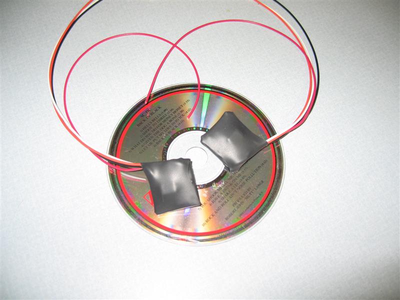
Wow, guess what I made a few of tonight?

They look good. I built up 12 so far. So here is the picture of the first generation. It's all surface mount. Which by the way is way too small. The next generation will be slightly bigger and longer and thinner. Over all size of gen 2 will be about 1.75 times bigger than what you see here. Surface mount made it super small, but it takes way too long to make any quanity of these, I was going a little carzy soldering these tonight. Not that any of you should care, as long as this thing works, right?

I just thought I would post a pic of the size and shape of what I got so far, I'm going to try to ship some of these tomorrow. Cross your fingers :)
Attached Files (1)
IMG_0134.JPG
IMG_0134.JPG
Page 1 of 8